Tutorial 6: Coordinate System
Overview
MMDetection3D uses three different coordinate systems. The existence of different coordinate systems in the society of 3D object detection is necessary, because for various 3D data collection devices, such as LiDAR, depth camera, etc., the coordinate systems are not consistent, and different 3D datasets also follow different data formats. Early works, such as SECOND, VoteNet, convert the raw data to another format, forming conventions that some later works also follow, making the conversion between coordinate systems even more complicated.
Despite the variety of datasets and equipment, by summarizing the line of works on 3D object detection we can roughly categorize coordinate systems into three:
Camera coordinate system – the coordinate system of most cameras, in which the positive direction of the y-axis points to the ground, the positive direction of the x-axis points to the right, and the positive direction of the z-axis points to the front.
           up  z front
            |    ^
            |   /
            |  /
            | /
            |/
left ------ 0 ------> x right
            |
            |
            |
            |
            v
          y down
LiDAR coordinate system – the coordinate system of many LiDARs, in which the negative direction of the z-axis points to the ground, the positive direction of the x-axis points to the front, and the positive direction of the y-axis points to the left.
             z up  x front
               ^    ^
               |   /
               |  /
               | /
               |/
y left <------ 0 ------ right
Depth coordinate system – the coordinate system used by VoteNet, H3DNet, etc., in which the negative direction of the z-axis points to the ground, the positive direction of the x-axis points to the right, and the positive direction of the y-axis points to the front.
          z up  y front
            ^    ^
            |   /
            |  /
            | /
            |/
left ------ 0 ------> x right
The definition of coordinate systems in this tutorial is actually more than just defining the three axes. For a box in the form of \((x, y, z, dx, dy, dz, r)\), our coordinate systems also define how to interpret the box dimensions \((dx, dy, dz)\) and the yaw angle \(r\).
The illustration of the three coordinate systems is shown below:
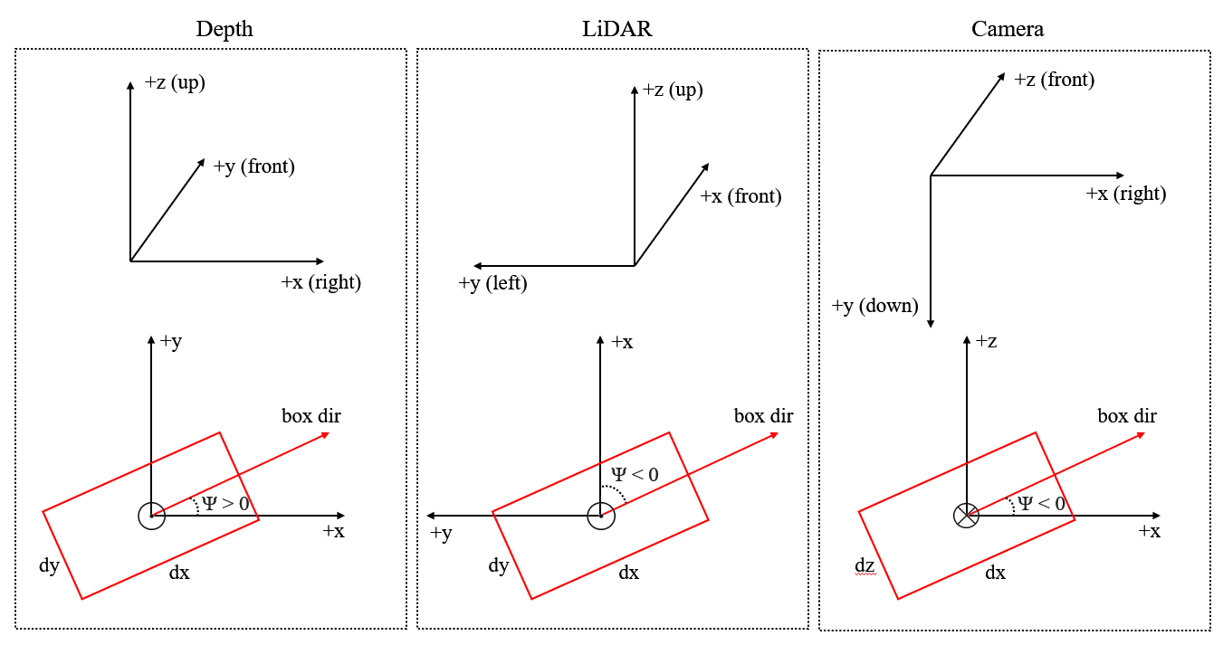
The three figures above are the 3D coordinate systems while the three figures below are the bird’s eye view.
We will stick to the three coordinate systems defined in this tutorial in the future.
Definition of the yaw angle
Please refer to wikipedia for the standard definition of the yaw angle. In object detection, we choose an axis as the gravity axis, and a reference direction on the plane \(\Pi\) perpendicular to the gravity axis, then the reference direction has a yaw angle of 0, and other directions on \(\Pi\) have non-zero yaw angles depending on its angle with the reference direction.
Currently, for all supported datasets, annotations do not include pitch angle and roll angle, which means we need only consider the yaw angle when predicting boxes and calculating overlap between boxes.
In MMDetection3D, all three coordinate systems are right-handed coordinate systems, which means the ascending direction of the yaw angle is counter-clockwise if viewed from the negative direction of the gravity axis (the axis is pointing at one’s eyes).
The figure below shows that, in this right-handed coordinate system, if we set the positive direction of the x-axis as a reference direction, then the positive direction of the y-axis has a yaw angle of \(\frac{\pi}{2}\).
                     z up  y front (yaw=0.5*pi)
                      ^    ^
                      |   /
                      |  /
                      | /
                      |/
left (yaw=pi)  ------ 0 ------> x right (yaw=0)
For a box, the value of its yaw angle equals its direction minus a reference direction. In all three coordinate systems in MMDetection3D, the reference direction is always the positive direction of the x-axis, while the direction of a box is defined to be parallel with the x-axis if its yaw angle is 0. The definition of the yaw angle of a box is illustrated in the figure below.
y front
  ^      box direction (yaw=0.5*pi)
 /|\        ^
  |        /|\
  |     ____|____
  |    |    |    |
  |    |    |    |
__|____|____|____|______\ x right
  |    |    |    |      /
  |    |    |    |
  |    |____|____|
  |
Definition of the box dimensions
The definition of the box dimensions cannot be disentangled with the definition of the yaw angle. In the previous section, we said that the direction of a box is defined to be parallel with the x-axis if its yaw angle is 0. Then naturally, the dimension of a box which corresponds to the x-axis should be \(dx\). However, this is not always the case in some datasets (we will address that later).
The following figures show the meaning of the correspondence between the x-axis and \(dx\), and between the y-axis and \(dy\).
y front
  ^      box direction (yaw=0.5*pi)
 /|\        ^
  |        /|\
  |     ____|____
  |    |    |    |
  |    |    |    | dx
__|____|____|____|______\ x right
  |    |    |    |      /
  |    |    |    |
  |    |____|____|
  |         dy
Note that the box direction is always parallel with the edge \(dx\).
y front
  ^     _________
 /|\   |    |    |
  |    |    |    |
  |    |    |    | dy
  |    |____|____|____\  box direction (yaw=0)
  |    |    |    |    /
__|____|____|____|_________\ x right
  |    |    |    |         /
  |    |____|____|
  |         dx
  |
Relation with raw coordinate systems of supported datasets
KITTI
The raw annotation of KITTI is under camera coordinate system, see get_label_anno. In MMDetection3D, to train LiDAR-based models on KITTI, the data is first converted from camera coordinate system to LiDAR coordinate system, see get_ann_info. For training vision-based models, the data is kept in the camera coordinate system.
In SECOND, the LiDAR coordinate system for a box is defined as follows (a bird’s eye view):
For each box, the dimensions are \((w, l, h)\), and the reference direction for the yaw angle is the positive direction of the y axis. For more details, refer to the repo.
Our LiDAR coordinate system has two changes:
The yaw angle is defined to be right-handed instead of left-handed for consistency;
The box dimensions are \((l, w, h)\) instead of \((w, l, h)\), since \(w\) corresponds to \(dy\) and \(l\) corresponds to \(dx\) in KITTI.
Waymo
We use the KITTI-format data of Waymo dataset. Therefore, KITTI and Waymo also share the same coordinate system in our implementation.
NuScenes
NuScenes provides a toolkit for evaluation, in which each box is wrapped into a Box instance. The coordinate system of Box is different from our LiDAR coordinate system in that the first two elements of the box dimension correspond to \((dy, dx)\), or \((w, l)\), respectively, instead of the reverse. For more details, please refer to the NuScenes tutorial.
Readers may refer to the NuScenes development kit for the definition of a NuScenes box and implementation of NuScenes evaluation.
Lyft
Lyft shares the same data format with NuScenes as far as coordinate system is involved.
Please refer to the official website for more information.
ScanNet
The raw data of ScanNet is not point cloud but mesh. The sampled point cloud data is under our depth coordinate system. For ScanNet detection task, the box annotations are axis-aligned, and the yaw angle is always zero. Therefore the direction of the yaw angle in our depth coordinate system makes no difference regarding ScanNet.
SUN RGB-D
The raw data of SUN RGB-D is not point cloud but RGB-D image. By back projection, we obtain the corresponding point cloud for each image, which is under our Depth coordinate system. However, the annotation is not under our system and thus needs conversion.
For the conversion from raw annotation to annotation under our Depth coordinate system, please refer to sunrgbd_data_utils.py.
S3DIS
S3DIS shares the same coordinate system as ScanNet in our implementation. However, S3DIS is a segmentation-task-only dataset, and thus no annotation is coordinate system sensitive.
Examples
Box conversion (between different coordinate systems)
Take the conversion between our Camera coordinate system and LiDAR coordinate system as an example:
First, for points and box centers, the coordinates before and after the conversion satisfy the following relationship:
\(x_{LiDAR}=z_{camera}\)
\(y_{LiDAR}=-x_{camera}\)
\(z_{LiDAR}=-y_{camera}\)
Then, the box dimensions before and after the conversion satisfy the following relationship:
\(dx_{LiDAR}=dx_{camera}\)
\(dy_{LiDAR}=dz_{camera}\)
\(dz_{LiDAR}=dy_{camera}\)
Finally, the yaw angle should also be converted:
\(r_{LiDAR}=-\frac{\pi}{2}-r_{camera}\)
See the code here for more details.
Bird’s Eye View
The BEV of a camera coordinate system box is \((x, z, dx, dz, -r)\) if the 3D box is \((x, y, z, dx, dy, dz, r)\). The inversion of the sign of the yaw angle is because the positive direction of the gravity axis of the Camera coordinate system points to the ground.
See the code here for more details.
Common FAQ
Q2: In every coordinate system, do the three axes point exactly to the right, the front, and the ground, respectively?
No. For example, in KITTI, we need a calibration matrix when converting from Camera coordinate system to LiDAR coordinate system.
Q3: How does a phase difference of \(2\pi\) in the yaw angle of a box affect evaluation?
For IoU calculation, a phase difference of \(2\pi\) in the yaw angle will result in the same box, thus not affecting evaluation.
For angle prediction evaluation such as the NDS metric in NuScenes and the AOS metric in KITTI, the angle of predicted boxes will be first standardized, so the phase difference of \(2\pi\) will not change the result.
Q4: How does a phase difference of \(\pi\) in the yaw angle of a box affect evaluation?
For IoU calculation, a phase difference of \(\pi\) in the yaw angle will result in the same box, thus not affecting evaluation.
However, for angle prediction evaluation, this will result in the exact opposite direction.
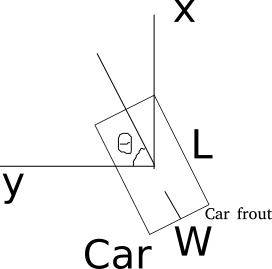
Just think about a car. The yaw angle is the angle between the direction of the car front and the positive direction of the x-axis. If we add \(\pi\) to this angle, the car front will become the car rear.
For categories such as barrier, the front and the rear have no difference, therefore a phase difference of \(\pi\) will not affect the angle prediction score.